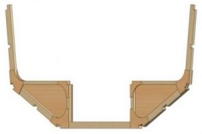
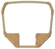
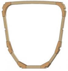
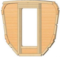
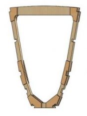
Due to the worldwide Coronavirus lockdown, the Class Globe 8.50 plans were initially distributed by email as Jpeg images with 1:10 scaled paper copies following in the post. On receipt, the first task was to print off the images and begin to understand the designer’s design intent. Following consideration, we decided that before any valuable marine ply is cut! We would start by converting the 2D plans into a 3D CAD model, this would allow the generation of CNC cut path files for panel manufacture speeding up the build process, moreover, the process of conversion would enable a virtual walk through the cabin helping our understanding of the build process.
Build Diary
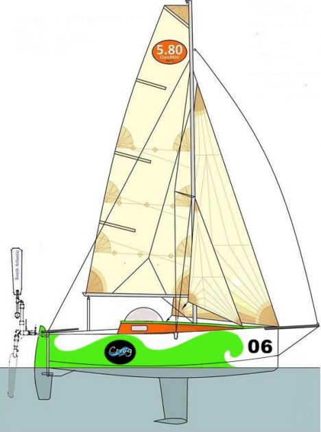
Converting Plans
Developing the lines
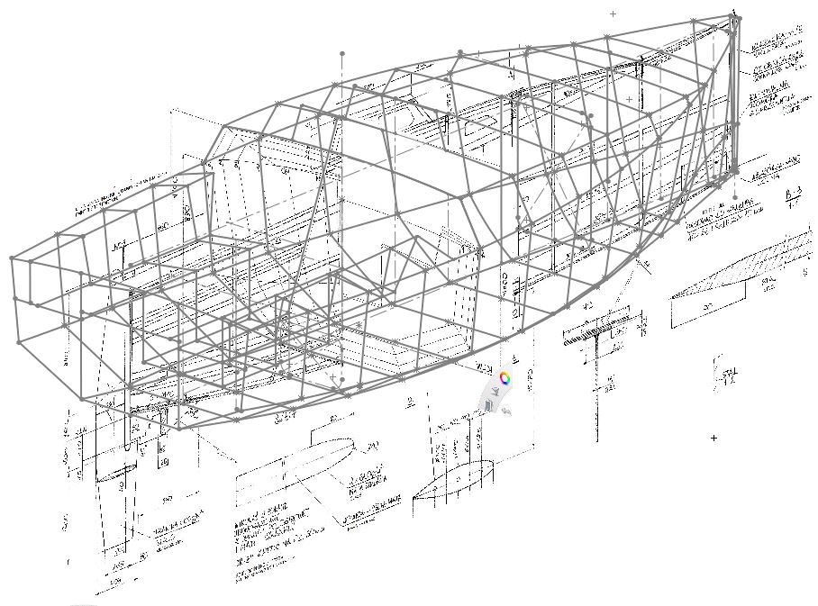
Time Log: 2 days
Cross-checking CAD dimensions with 1:10 paper drawings
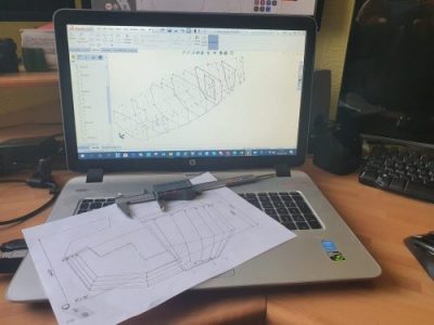
Note: Scaling by this method is only as accurate as of the printed drawing, line thickness etc. plus your measuring ability, as for every 1mm error will result in +/- 10mm on the final build, so always measure from a fixed datum i.e. KLW for vertical and P “transom” for horizontal dimensions, don’t scale measure from feature to feature as indicated on the plans, else you may find your build to be out of class!
Time Log: 1/2 day
Lines into surfaces
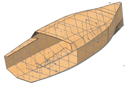
Time Log: 1 – 1/2 days
Pod Design
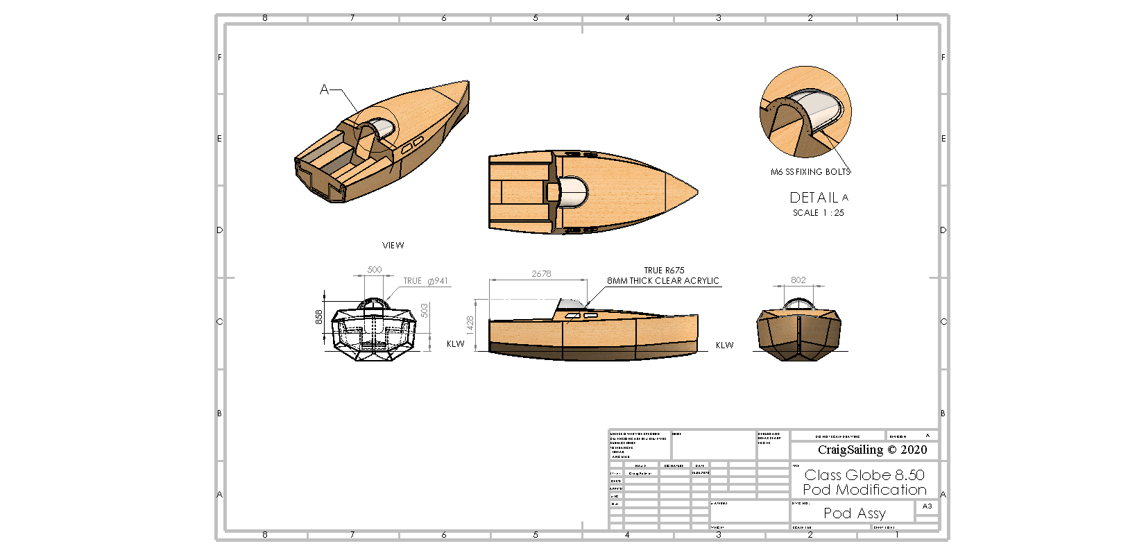
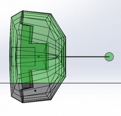
An investigation into alternative Pod/Dome design
Time Log: 2 days
Adding in the cockpit
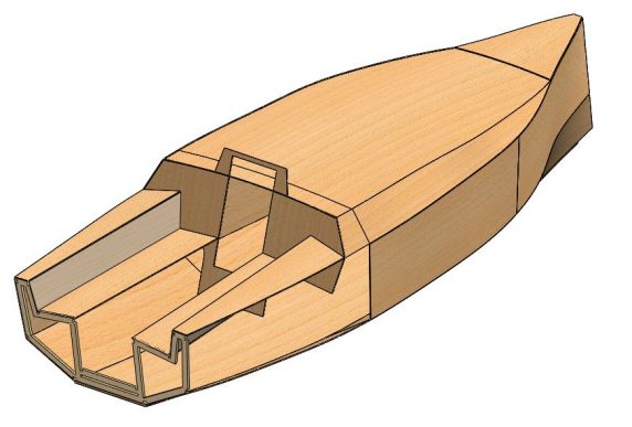
Cockpit Drain Holes
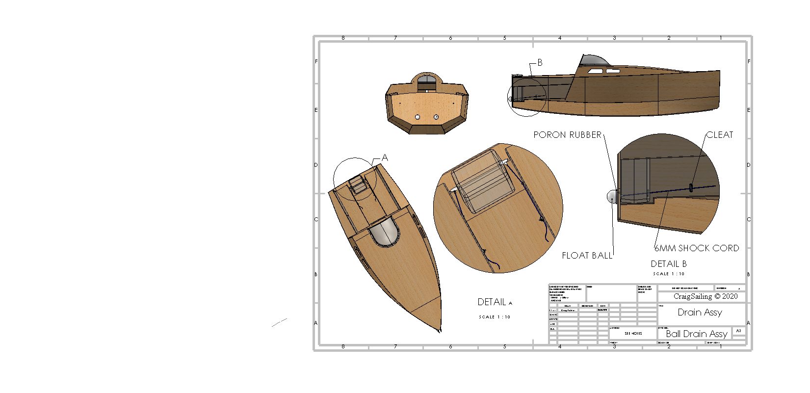
An investigation into cockpit drain hole covers
Time Log: 1/2 day
Keel Assembly
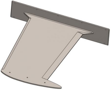
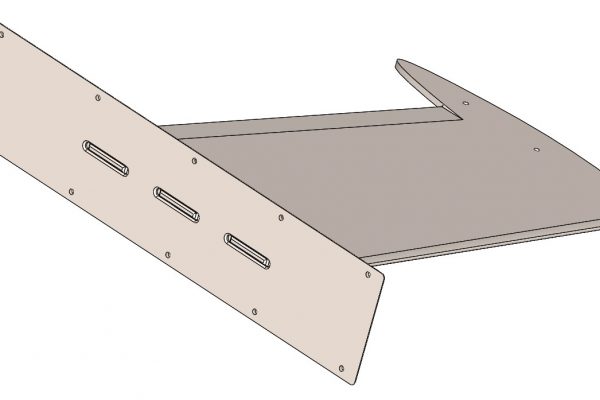
Keel & Top Plate 3D CAD models.
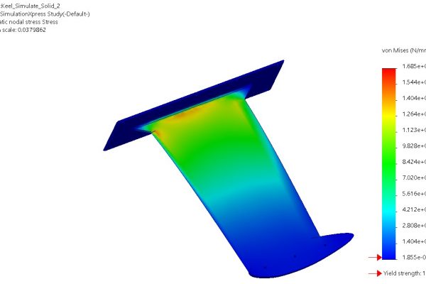
Top plate Lug design and welds, calculation and assessment of working Stress.
Time Log: 1 day
Frame Assemblies
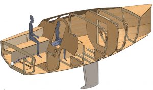
3D CAD design of frames and keel beams.
Time Log: 10 days
